Model NO.: JH-LWGY-HP
Measuring Media: Liquid
Measuring Principle: Mechanics
Measurement Object: Closed Pipeline
Certification: CE, RoHS, ISO
Display: None
Temperature: -20c~120c
Power Supply: 24VDC or Battery
Output Signal: 4-20mA, Pulse, RS485
Body Materia: Ss304/Ss316
Connection: Flange or Screw Thread/Hausman
Pressure: 25MPa
Trademark: JH
Transport Package: Carton/Wooden Case
Specification: CE, ISO
Origin: Shanghai
HS Code: 9026100000
Â
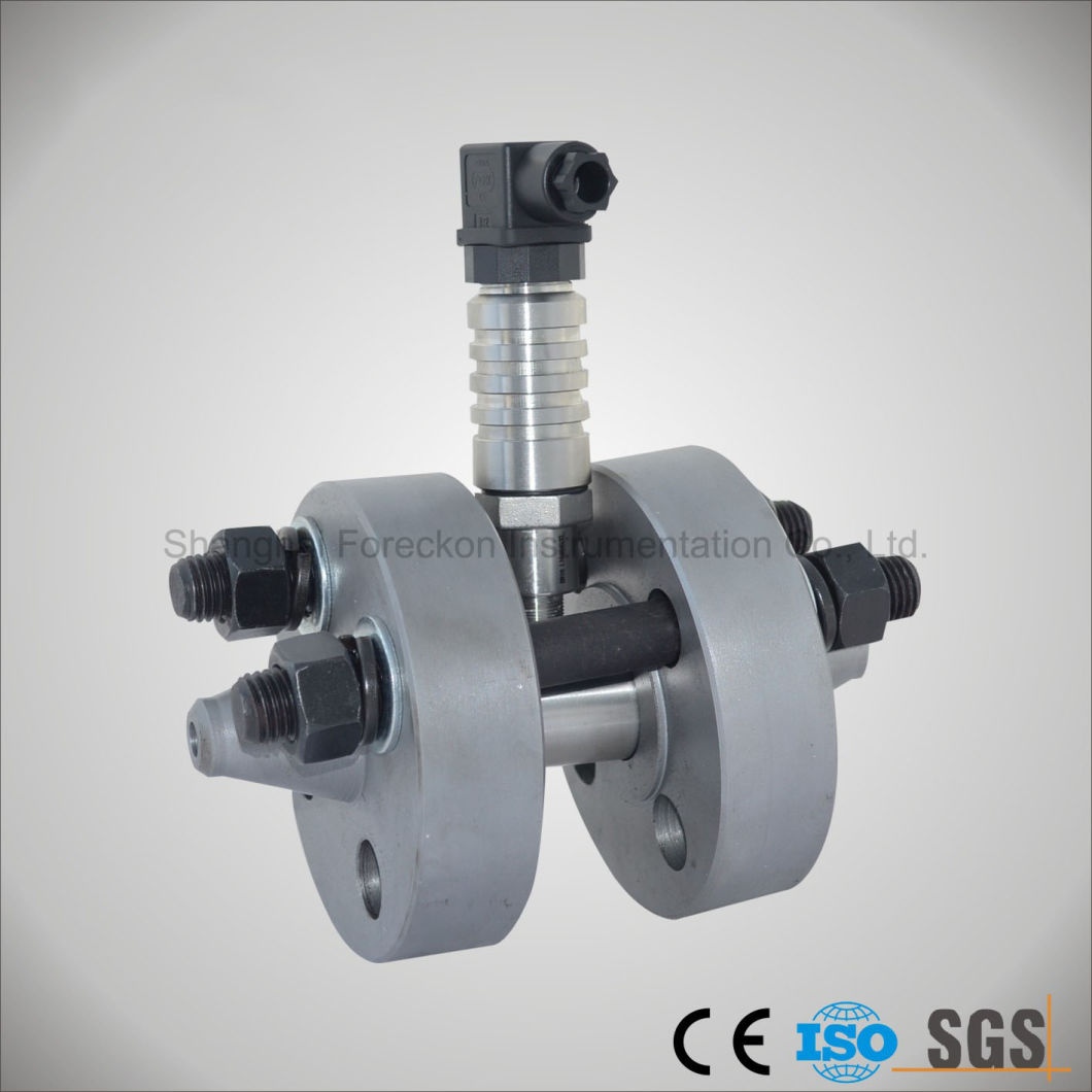
Liquid Turbine Flowmeter

Â
Â
Main Applications:
Turbine flow flowmeter adapts to measure the liquid rate and total flow rate of low viscosity, It can be widely used in the fields of Petrol,fuel ,water ,chemical industry,Metallurgy,Scientific research for measuring or control Several output and display methods can be selected.
Â
Features:
- Pulse output, linear feature;
- High accuracy, sensitive reaction;
-Wide measuring range;
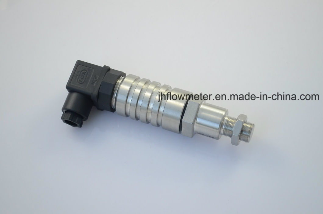
-Signal output
- Simple structure, easy installation, operation and maintenance;
-Filter, eliminator and rectifier(aligner) can be provided as a whole package;
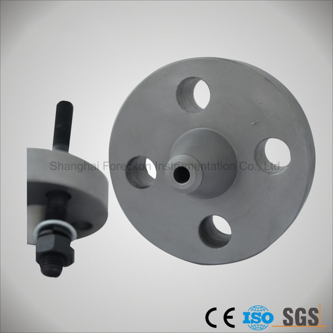
- A pair of companion vice flanges for installation is available.
Â
Technical parameters:
Table 3-1
| Nominal Diameter DN(mm) |
Range(m3/h) | Liquid Temperature (ºC) |
Nominal Pressure PN(MPa) |
Ambient Temp. (ºC) |
Humidity (%) |
Max. Pressure Loss (MPa) |
|||||
| Error  0.2%* |
Error   0.5% | Error     1% | |||||||||
| Min. | Max. | Min. | Max. | Min. | Max. | ||||||
| 2* | Â | Â | Â | Â | 0.03 | 0.16 | -20 Â to +120 |
6.3 | -25 to +55 |
≤ 80 | 0.15 |
| 4* | Â | Â | Â | Â | 0.04 | 0.25 | 0.12 | ||||
| 6 | Â | Â | 0.1 | 0.6 | 0.1 | 0.6 | 6.3 16 25 32* |
0.08 | |||
| 10 | Â | Â | 0.25 | 1.2 | 0.2 | 1.2 | 0.05 | ||||
| 15 | 1.2 | 6 | 0.6 | 4 | 0.6 | 6 | 0.035 | ||||
| 25 | 2 | 10 | 1.6 | 10 | 1 | 10 | |||||
| 40 | 4 | 20 | 3 | 20 | 2 | 20 | 1.6 2.5 |
0.025 | |||
| 50 | 6 | 40 | 4 | 40 | 4 | 40 | |||||
| 80 | 16 | 100 | 10 | 100 | 10 | 100 | |||||
| 100 | 25 | 160 | 20 | 160 | 20 | 200 | 1.6 2.5 |
||||
| 150 | 50 | 300 | 40 | 300 | 40 | 400 | |||||
| 200 | 150 | 750 | 100 | 600 | 80 | 800 | |||||
| 250* | 200 | 1000 | 160 | 1000 | 120 | 1200 | 1.6 | ||||
| 300* | Â | Â | 260 | 1600 | 180 | 1800 | |||||
Â
Table 3-2 Model and Specification Code
| Model | Specification Code | Description | |||||||||
| LW....................................................................................... | Turbine Flowmeter Transducer For Liquid |
||||||||||
| Â | G........................................................................ | ||||||||||
| Â | Y...................... | ||||||||||
| Nominal Diameter | -2*................................................. -4*................................................. -6.................................................. -10................................................ -15................................................ -25................................................ -40................................................ -50................................................ -80................................................ -100.............................................. -150.............................................. -200.............................................. -250.............................................. -300.............................................. |
2mm(PT G3/8″) 4mm(PT G3/8″) 6mm(PT G3/8″) 10mm(PT G1/2″) 15mm(PT G1″) 25mm(PT G11/4″) 40mm(Flange) 50mm(Flange) 80mm(Flange) 100mm(Flange) 150mm(Flange) 200mm(Flange*) 250mm(Flange*) 300mm(Flange) |
|||||||||
| Type Code | A............................ .......... B............................ .......... C............................ ....... |
Accuracy 1% Accuracy 0.5% Accuracy 0.2%* |
|||||||||
| Output Signal | P......................... ....... I.......................... ....... T......................... ....... M........................ ....... |
Pulse Analog 4 to 20mA Total display(Battery. for 2 to 3 years) Pulse out/4 to 20mA out and LCD display(Intelligent) |
|||||||||
| Diameter Pressure | C1................... ..... C2................... ..... C3................... ..... C4................... ..... C5................... ..... C6................... ..... C7................... ..... |
PN1.6MPa PN2.5MPa PN4.0MPa PN6.3MPa PN16MPa(Diameter≤25mm) PN25MPa(Diameter≤25mm) PN40MPa*(Diameter≤25mm) |
|||||||||
| Explode Request | /NE /EX |
Not Explosive Ex ib I or Ex dIIBT4 |
|||||||||
| Range of Temperature | /NT /HT |
Normal Temperature(<120ºC) High Temperature(≥120 to 150ºC) |
|||||||||
| Special Option | / | e.g.:High Temperature,Erode-resistant,Wearable etc. | |||||||||
| Â | Â | Â | Â | Â | Â | Â | Â | Â | Â | Â | Â |
             2. Mark "*" means apecial order.
Â
Floor Deck Roll Forming Machine Series
Golden Integrity Roll Forming Machine Co., Ltd. , http://www.hbrollformingmachine.com