Key words: crude oil metering, large diameter flowmeter, failure rate, measurement accuracy Large diameter flowmeter is a metering device manufactured by Shanghai Instrument No. 9 Plant in 1973. An oil field supplies crude oil to a petrochemical company's refinery every year. Most of the metering equipment is To measure. The oil fields used to transport crude oil to refineries are three large-caliber screed flowmeters. They work at the same time as the three large caliber flowmeters of the refinery. If the measurement is inaccurate due to equipment failure, both parties will check the other equipment. In most cases, Loss of the equipment will occur if the equipment fails. Therefore it is particularly important to reduce the failure of metering equipment. Three large-diameter flowmeters installed in the crude oil metering plant of a refinery have been operating for more than 30 years. Equipment wear has been severe and failures have occurred. This has seriously affected the measurement accuracy of crude oil and caused huge economic losses to petrochemical companies each year. Since manufacturers stopped producing this type of instrument 10 years ago, it is impossible to obtain the support of manufacturers from the aspect of technology and accessories, which has brought difficulties to our daily maintenance work. In order to ensure the normal operation of production and ensure the accuracy of measurement, the failure rate of the primary transmission system of the flowmeter must be reduced.
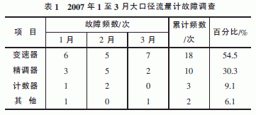
1 Current Status Survey 1.1 Current Status Survey 1 (See Table 1)
From Table 1, it can be seen that the failure of the primary transmission system is the main reason that affects the measurement accuracy.
1.2 Current Status Investigation The second-level transmission system is the main component of the large-diameter flowmeter. It consists of a metering box, upper and lower end caps, an active waist wheel and a driven waist wheel. It directly contacts the medium and is affected by speed, high temperature and other factors. Faults occur frequently. In order to find out the cause of the failure, a follow-up survey was conducted. Table 2 is the collation of the follow-up survey data from April to June.

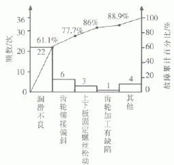
From the arrangement chart, it can be seen that poor lubrication is a major factor causing frequent transmission failures.
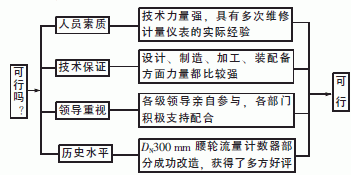
2 Determination of objectives and feasibility analysis Based on the status quo, we have determined the goal of reducing the transmission failure rate from the current 54.5% to 5% or less. The feasibility analysis is shown in Figure 2.
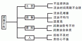
3 To analyze, confirm, and verify a total of nine end-of-line factors for poor lubrication problems (see Figure 3), use the importance scoring method to evaluate, and find four main factors, and conduct direct observation at the site for verification, as shown in Table 3. .
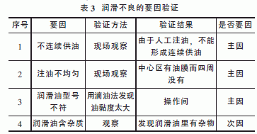
4 Formulation of countermeasures Based on the above main factors, corresponding countermeasures have been formulated (see Table 4).
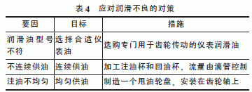
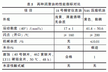
5 Implementation 5.1 Implementation One of the compressor oils with viscosity of N46 was originally used in the transmission. The lubrication effect is not satisfactory. For the characteristics of fast transmission speed and high temperature, we have re-selected the 18th precision instrument oil. Table 5 is two types of lubrication. Comparison of oil performance indicators.
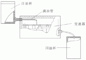
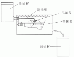
5.2 Implementation of the second transmission oil supply has always been done manually 24h. In order to ensure continuous oil supply, we installed a pair of D50mm×120mm oil injection cups and oil return cups on the transmission case. According to the kinematic viscosity of lubricating oil, after several tests, we chose a filling pipe with a diameter of 2mm to ensure 6 The amount of oil drip/min ensures continuous oil supply, see Figure 4.
5.3 Implementation of the three continuous oil supply problem has been solved, but there are more than 20 gear shafts on the transmission, distributed on the D120mm disc, and there are many shafts on the outer part, which has the problem of non-uniform oil supply. We have extended the central axis and installed an oil pan on the central axis. Many small holes were drilled in the pan. With the high-speed rotation of the central axis, the lubricant spreads around to achieve the purpose of uniform oil supply. 5.
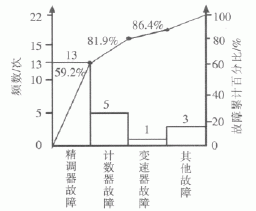
6 Effect Inspection After taking measures, we investigated the faults of large-caliber flowmeters from August to October of 2007. See Figure 6.
Description:
AWS E6010 Welding Electrodes It shows a very good performance in welding of all positions, especially vertical down welding. is a high cellulose sodium type carbon steel welding electrode for vertical down welding. The welding performances are excellent: dep penetration , fewer slag, slag easy to remove, high welding efficiency and good weld shape etc. The electrode forms double sides by one side welding.
Application:
AWS E6010 Welding Rod is suitable for welding root passes, hot passes, filler and cover passes as well as for capping of general pipes and similar structures.
Product details:
Diameter: 2.0mm, 2.5mm, 3.2mm, 4.0mm, 5.0mm
Length: 300mm, 350mm, 400mm, 450mm
Operating Current: AC and DC
Welding Current Range:60-160A
Packing:
2.5mm*300mm 2.5kgs/inner box, 8inner boxes/carton=20kgs
3.2mm*350mm 5.0kgs/inner box, 4inner boxes/carton=20kgs
4.0mm*400mm 5.0kgs/inner box, 4inner boxes/carton=20kgs
5.0mm*400mm 5.0kgs/inner box, 4inner boxes/carton=20kgs
Attention:
1. AWS E6010 Carbon Steel Welding Electrodes, Generally, welding electrodes do not need bake before welding.
2. If damped, the Aws E6010 Welding Electrodes should be baked for 0.5-1 hour at the temperature of 70-80℃ before welding.
AWS E6010 Welding Electrodes
Aws E6010 Welding Electrodes,Low Hydrogen Welding Electrode,E6010 Welding Electrode,6010 Welding Rod
Dingzhou Jinlong Metal Production Co., Ltd. , http://www.weldingelectrodefactory.com