0 Introduction The circulating water system is the "blood" of a thermal power plant and its performance directly affects the output of the generating unit. Maoming Thermal Power Plant originally designed 2 sets of 100MW units to run in parallel when 3 sets of circulating pumps supply water, about 30,000m3; 1 set of 100MW sets when full load operation, 1 pump water supply can not meet the unit operation requirements, when the power grid peak load is low, 1 The pump water supply can meet the requirements, but the water supply of the oil cooler cannot be guaranteed due to the low water pressure. Under normal circumstances, a 100MW unit is running, both pumps are supplied with water and the outlet pressure is 0.088MPa to 0.090MPa. Under normal circumstances, the unit can bring about 600 MW of load when one circulating pump supplies water. In order to save plant power and improve the automation level of the power plant, frequency conversion speed control is adopted for circulating pumps. This paper designs and develops a high-voltage variable frequency speed control system for circulating pumps, and proposes and implements a control strategy for “optimum vacuum†in the circulating water system.
After the demonstration, high-high high-voltage frequency converter is used to regulate the speed of the No. 4 unit circulating pump: when two 100MW units are running at full load, three pumps are connected in parallel and the frequency converter does not regulate operation; when the unit is low When the load is running, the frequency converter regulates the operation; when a 100MW unit is running at full capacity, two pumps are running and the frequency converter regulates the operation; when the winter and spring seasons, when the unit is peaking and running, if a pump can be supplied with water, The frequency converter can be taken out of operation.
The scope of regulation of circulating water volume is currently controlled by the condition of the oil cooler in addition to the influence of the unit load, and there is no linkage device between the start switch of the circulating pump and the outlet valve, and they operate independently. After frequency conversion speed regulation, the process of requiring the inverter to switch to mains control is dynamic and infinite. The control parameters of the circulating water system are: flow, water pressure, liquid level in the front tank, liquid level in and out of the water channel, turbine load, and vacuum. Because the circulating pump is a constant power load, the “optimal vacuum†controller continuously adjusts the circulating water volume according to the changes of the turbine load and vacuum to ensure the “optimal vacuum†and optimize the efficiency of the turbine. In this way, not only plant power is saved, but also the automation level of the power plant is increased, and the goal of saving energy and reducing consumption of thermal power plants is achieved.
1 Working Principle of Circulating Water System The circulating water system structure of Unit 4 in Maoming Thermal Power Plant is shown in Figure 1. The basic parameters of the system are: circulating water pump model is 40ZLQ50, flow rate is 8460m3/h~12200m3/h(-8°~-20°), head is 10.5m~12.2m, speed is 585r/min; drive motor model is JSLl5-10M, rated Power 480kW, rated voltage 6kV, rated current 61A, actual operating current 59A ~ 62A, motor connection mode is Y type, power factor 0.77, insulation class B; on-site environment temperature 0 ~ 40 °C, humidity 97%.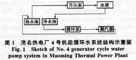
The circulating water pump system has been transformed into a fully-closed cycle since the end of 1997. The pressure of the circulating water pump outlet at the front of the machine room is 10m to 12m water column, and the condenser is hit from the inflow channel, and the drainage channel is drained to the front of the cooling tower booster pump. After the pressure is raised by the booster pump (the outlet pressure is 16.9m water column) Cooling towers were sent to cool the water (9 °C ~ 12 °C) after the cooling water from the aqueduct back to the engine room before the circulating water pump population, hit the condenser, so continue to cycle.
The operation of the circulating pump is mainly controlled by the remote operation of the 8m control room. The circulating water pump and condenser inlet and outlet doors are also controlled by remote controls to open, close and adjust. The water balance control of the circulating water and booster water system is performed on the adjustment of the water level of the inlet and return channels. The key point is that the water level of the booster pump before the inlet of the booster pump is higher than the overflow level, resulting in overflow of the hot water and affecting the operation. Economical. The balance adjustment of water quantity (water level) is mainly based on the amount of water needed for unit operation, using the combination of pump operation mode and the condenser's drainage door to coarsely adjust, and the command of the steam turbine operation supervisor is executed according to the instruction value of the dial water level. Fine adjustment, it is difficult to achieve absolute balance of water. The booster pump system is a post-positioning part of the circulating water system in Maoming Thermal Power Plant. The 3500m2 and 5500m2 cooling tower booster pumps are provided. The start and stop of the control is performed by the operator through the dial remotely. 12000HLCQ3.25-17 Booster pump outlet is provided with energy storage type hydraulic (hydraulic pressure) check door. When the pump is opened, the switch is closed firstly, and after the linkage outlet check door is opened, the water pump motor is restarted. The same is true for stopping the pump. The purpose is to prevent the pump from turning over.
2 High-voltage frequency conversion speed control system The main advantages of high-voltage frequency conversion speed regulation are as follows:
a. Soft start, that is, the starting current slowly rises from 0 to the rated value, which can reduce the impact on the power grid and the loss of mechanical equipment;
b. Modern frequency converters use semiconductor modules and their drivers and control modules. The number of components is small, the reliability is high, and the frequency converter has a low failure rate. Even if a fault occurs, it can self-diagnose and display the cause of the fault so that it can be eliminated in time.
c. The frequency converters all have standard interfaces for connection with the micro-machine system for optimal operation.
d. The small frequency converter has complete protection functions and can protect the motor from current, voltage, temperature and other aspects.
The high-voltage variable frequency speed control system adopts direct high-high and ROBICON's perfect harmonic high-voltage inverter (480kW/6kY). The inverter can dynamically input, adjust, and withdraw from a circulating pump. In the 8m control room or local control panel to achieve the remote adjustment of the inverter operation; inverter device is installed on the standby pump, the site of the installation, interface, commissioning time can be arranged relatively longer; current circulating pump start switch and outlet valve No linkage devices, each operating independently. The process of inverter switching to mains control is dynamic and infinite.
Maoming thermal power plant is located in South China. Due to the special geographical environment, it has special requirements for the environmental adaptability of high-voltage frequency converters.
a. Humidity requirements: The humid climate in South China requires that high-voltage inverters be able to operate in an environment with a humidity of at least 98%.
b. Temperature requirements: High-voltage inverters must ensure long-term continuous full-load operation under the temperature limits specified in the technical specifications;
c. Gas Requirements: The operating environment of high voltage inverters has strict requirements for various dusts.
3 Control System Function The structure of the circulating water pump control system is shown in Figure 2. The controller consists of PLC (programmable controller) system and IPC (industrial control computer) system, and the control system is installed in the control room of the circulating pump room. The operator can choose to operate the circulation pump system in the main control room (distant), PLC control cabinet (in situ) and IPC upper computer.
The main working methods of circulating water pump control system are as follows:
a. Two 100MW units are running at the same time, three pumps of circulating water are connected in parallel, and three pumps of booster pumps are running. The combination of the pumps is adjusted to correspond to maintain the water level roughly balanced.
b. One 100 MW unit is out of service and the other 100 MW unit is running. Because the current installation of the oil cooler has a high installation elevation, it needs to ensure a certain inlet pressure and maintain its cooling effect, so it still needs 2 pumps to run, even if it is low. The same applies to load peaking.
c. After installing the adjustable frequency speed control of the inverter, there is always one frequency conversion pump driven during peaking and two pump operations. In other cases, the variable frequency speed control system can be withdrawn or selected.
The control system will continuously adjust the cooling circulating water volume according to the changes of the turbine load and vacuum, by controlling the different combinations of circulating water pump and booster pump and using the high-voltage inverter to control the output of the circulating pump to ensure that the cold and hot water pools do not overflow. Under the control of the condenser condenser vacuum is optimal to achieve energy-saving purposes.
The precautions and parameters in the various operating modes of the circulating water pump control system are as follows:
a. Circulating water pump and booster pump flow should be basically balanced to avoid overflow of hot water to cold water channels.
b. Ensure that the oil cooler has a certain inlet pressure.
c. Under normal circumstances, a circulating water pump water supply unit can bring about 60MW load. When two 100MW units are operating at full load, three pumps are connected in parallel and the frequency converter does not regulate the operation; when the unit is at peak load and low load operation, the frequency converter regulates the operation; when a single 100MW unit is running at full capacity, two pumps Operation, the frequency converter regulates the operation; When the winter and spring season, when the unit is peaking and running, if can make 1 pump water supply, the frequency converter can quit running. The scope of regulation of the circulating water volume is currently controlled by the operating conditions of the oil cooler in addition to the influence of the unit load.
d. The retrofitted circulating pump cannot be operated only in the regulation state.
e. The control parameters of the circulating water pump are: flow, water pressure, liquid level in the front tank and inlet and outlet channels.
f. The average annual running time of the pump is about 5500h.
g. The elevation of the embankment in the hot and cold water pools is 29.2m; the condenser vacuum gauge is used for real measurement.
h. The control system can provide signals and indication values ​​such as booster pump flow, front tank water level, canal water level, circulating pump flow, condenser cooling water demand, and vacuum, and can guide the operation of circulating water and booster water systems.
3.1 Functions of PLC System PLC realizes all logic control functions of the optimal energy-saving controller of the circulating water system. The main functions of the PLC system are as follows:
a. Realize the start and stop program control of the circulation pump and its ancillary equipment;
b. Realize the opening and closing program control and linkage function of the circulation pump outlet door and communication door;
c. To achieve the temperature, water level and other protection of the three elections two control logic, in the premise of ensuring the "vacuum optimal" under the control of the inverter so that the hot water pool does not overflow;
d. The first memory logic function to realize important faults;
e. Failure of PLC system, IPC host computer crash and restart should not affect the system control logic;
f. The control system reserves a standard interface for communication with the DCS;
g. The system has a fault signal that requires sound and light alarms in the PLC control cabinet, IPC, and main control room.
3.21 Functions of the PC System The main functions of the IPC system are management functions such as operation, recording, display, and query.
a. Start, stop and switch the valves of each pump through IPC;
b. The system diagram is the main screen for the operator to monitor and operate the equipment;
c. Click on a device in the system diagram to operate, and it is necessary to have the “help†prompt to start/stop the device;
d. The on-off state of the waterway, the sealed waterway and the oil circuit, and the valve on the system diagram should have obvious color distinction;
e. The work, stop, and fault conditions of the equipment on the system diagram should be clearly distinguished by color;
f. The real-time data and engineering unit display of the analog measurement point on the system diagram;
g. The system has the function of recording the operation of the operator, and the recording time requirement is accurate to the second level;
h. The system has a recording function for all input/output switch signals;
i. The system has an analog trend graph display function, the historical trend of the storage period is 1 week;
j. The system has real-time display and accident recall functions for all alarm and fault trip signals.
4 Implementation of the control system 4.1 Implementation of the PLC system The reliability of the circulating water system is crucial. Therefore, its control system also requires extremely high reliability. According to the requirements of the system, Schneider's Quantum series of PLC systems with dual-system hot standby functions are selected as the core controller. The PLC dual-system hot standby system represented by Japan's OMRON Corporation is actually "warm standby". It is to put two CPU modules on a single substrate; and the PLC double-system hot standby system represented by Schneider is 2 sets of PLC systems are hot standby each other and have higher reliability.
As shown in Fig. 3, the circulating water pump control system configuration consists of a dual-system hot standby PLC system and an IPC system. In the PLC system, the CHS unit is a dual-unit hot standby unit, which is connected through an optical fiber; the CPU unit and the IPC system are composed of a shielded twisted pair cable and a MB+ network with a transmission rate of 1 Mbit/s; the CRP unit and the CRA unit constitute a remote I/O control system. , Connected via coaxial cable; CPS is a power module unit. 4.2 Implementation of IPC System The IPC upper computer system completes the issuing of all control commands, the display of device status, and the query of signals. The monitoring software of the IPC system selects Kingview 6.0 of Beijing AMC, and communicates with the PLC system through the SA85 network card to form an MB+ network, which satisfactorily fulfills the functions required by the system. For reliable operation, the system installs Windows NT as an operating system. IPC IPC chose Advantech's PIII-866 model (40GB hard disk) and the monitor selected Philips flat panel display.
The circulating water pump control system also reserves the MB+ network communication interface for DCS to prepare for the expansion of the control system.
Circulating water pump control system main program block diagram shown in Figure 4.
4.3 "Optimal vacuum" controller "Optimum vacuum" is obtained by selecting steam turbines with steam turbine population of 60%, 70%, 80%, 85%, 90% and 100% load. The pressure/temperature is not changed, the degree of supercooling of the water is guaranteed to meet the requirements, and the circulating water flow is adjusted (through frequency conversion speed regulation, and can also be measured on a system before frequency conversion is used), and the best thermal efficiency curve of the turbine is measured. Comprehensively considering the mechanical characteristics of the turbine and the optimum efficiency, the corresponding condenser vacuum obtained is the “optimal vacuumâ€. At this time, the speed of the circulating pump ensures that the operating state of the turbine is optimized under the “optimal vacuumâ€.
The measurement of “optimal vacuum†is based on the seasons. At least it must be measured in winter and summer respectively. Winter is measured around January and summer is measured around July and August. Each measurement point must ensure that the system can operate normally for 2h to 4h. Measurement data must be converted to standard operating conditions. The post-processing of the measurement data is also very important. A variety of factors are used to fit the curve, and the singularity point is specifically analyzed. If necessary, the data of this point must be re-measured. The measurement of "optimal vacuum" can be done by the power plant itself, or it can be conducted by a pilot plant or a thermal plant. The measurement method is different according to the structure of the circulating water system, the configuration of the condenser, and the output conditions of the high and low pressure cylinders. The method of this article is for reference only.
5 Conclusion This article designed and developed the Maoming Thermal Power Plant No. 4 unit circulating pump high frequency variable frequency speed monitoring and control system. The control system realizes the control strategy of the optimal energy-saving controller of the circulating water system by controlling the changes of the turbine load and the vacuum, controlling the different combinations of the circulating pump and the booster pump, and using the high-voltage inverter to control the output of the circulating pump. Under the premise that the cold and hot water pools do not overflow, the vacuum degree of the condenser of the generator set is controlled optimally, and the purpose of energy saving is achieved.
After the demonstration, high-high high-voltage frequency converter is used to regulate the speed of the No. 4 unit circulating pump: when two 100MW units are running at full load, three pumps are connected in parallel and the frequency converter does not regulate operation; when the unit is low When the load is running, the frequency converter regulates the operation; when a 100MW unit is running at full capacity, two pumps are running and the frequency converter regulates the operation; when the winter and spring seasons, when the unit is peaking and running, if a pump can be supplied with water, The frequency converter can be taken out of operation.
The scope of regulation of circulating water volume is currently controlled by the condition of the oil cooler in addition to the influence of the unit load, and there is no linkage device between the start switch of the circulating pump and the outlet valve, and they operate independently. After frequency conversion speed regulation, the process of requiring the inverter to switch to mains control is dynamic and infinite. The control parameters of the circulating water system are: flow, water pressure, liquid level in the front tank, liquid level in and out of the water channel, turbine load, and vacuum. Because the circulating pump is a constant power load, the “optimal vacuum†controller continuously adjusts the circulating water volume according to the changes of the turbine load and vacuum to ensure the “optimal vacuum†and optimize the efficiency of the turbine. In this way, not only plant power is saved, but also the automation level of the power plant is increased, and the goal of saving energy and reducing consumption of thermal power plants is achieved.
1 Working Principle of Circulating Water System The circulating water system structure of Unit 4 in Maoming Thermal Power Plant is shown in Figure 1. The basic parameters of the system are: circulating water pump model is 40ZLQ50, flow rate is 8460m3/h~12200m3/h(-8°~-20°), head is 10.5m~12.2m, speed is 585r/min; drive motor model is JSLl5-10M, rated Power 480kW, rated voltage 6kV, rated current 61A, actual operating current 59A ~ 62A, motor connection mode is Y type, power factor 0.77, insulation class B; on-site environment temperature 0 ~ 40 °C, humidity 97%.
The circulating water pump system has been transformed into a fully-closed cycle since the end of 1997. The pressure of the circulating water pump outlet at the front of the machine room is 10m to 12m water column, and the condenser is hit from the inflow channel, and the drainage channel is drained to the front of the cooling tower booster pump. After the pressure is raised by the booster pump (the outlet pressure is 16.9m water column) Cooling towers were sent to cool the water (9 °C ~ 12 °C) after the cooling water from the aqueduct back to the engine room before the circulating water pump population, hit the condenser, so continue to cycle.
The operation of the circulating pump is mainly controlled by the remote operation of the 8m control room. The circulating water pump and condenser inlet and outlet doors are also controlled by remote controls to open, close and adjust. The water balance control of the circulating water and booster water system is performed on the adjustment of the water level of the inlet and return channels. The key point is that the water level of the booster pump before the inlet of the booster pump is higher than the overflow level, resulting in overflow of the hot water and affecting the operation. Economical. The balance adjustment of water quantity (water level) is mainly based on the amount of water needed for unit operation, using the combination of pump operation mode and the condenser's drainage door to coarsely adjust, and the command of the steam turbine operation supervisor is executed according to the instruction value of the dial water level. Fine adjustment, it is difficult to achieve absolute balance of water. The booster pump system is a post-positioning part of the circulating water system in Maoming Thermal Power Plant. The 3500m2 and 5500m2 cooling tower booster pumps are provided. The start and stop of the control is performed by the operator through the dial remotely. 12000HLCQ3.25-17 Booster pump outlet is provided with energy storage type hydraulic (hydraulic pressure) check door. When the pump is opened, the switch is closed firstly, and after the linkage outlet check door is opened, the water pump motor is restarted. The same is true for stopping the pump. The purpose is to prevent the pump from turning over.
2 High-voltage frequency conversion speed control system The main advantages of high-voltage frequency conversion speed regulation are as follows:
a. Soft start, that is, the starting current slowly rises from 0 to the rated value, which can reduce the impact on the power grid and the loss of mechanical equipment;
b. Modern frequency converters use semiconductor modules and their drivers and control modules. The number of components is small, the reliability is high, and the frequency converter has a low failure rate. Even if a fault occurs, it can self-diagnose and display the cause of the fault so that it can be eliminated in time.
c. The frequency converters all have standard interfaces for connection with the micro-machine system for optimal operation.
d. The small frequency converter has complete protection functions and can protect the motor from current, voltage, temperature and other aspects.
The high-voltage variable frequency speed control system adopts direct high-high and ROBICON's perfect harmonic high-voltage inverter (480kW/6kY). The inverter can dynamically input, adjust, and withdraw from a circulating pump. In the 8m control room or local control panel to achieve the remote adjustment of the inverter operation; inverter device is installed on the standby pump, the site of the installation, interface, commissioning time can be arranged relatively longer; current circulating pump start switch and outlet valve No linkage devices, each operating independently. The process of inverter switching to mains control is dynamic and infinite.
Maoming thermal power plant is located in South China. Due to the special geographical environment, it has special requirements for the environmental adaptability of high-voltage frequency converters.
a. Humidity requirements: The humid climate in South China requires that high-voltage inverters be able to operate in an environment with a humidity of at least 98%.
b. Temperature requirements: High-voltage inverters must ensure long-term continuous full-load operation under the temperature limits specified in the technical specifications;
c. Gas Requirements: The operating environment of high voltage inverters has strict requirements for various dusts.
3 Control System Function The structure of the circulating water pump control system is shown in Figure 2. The controller consists of PLC (programmable controller) system and IPC (industrial control computer) system, and the control system is installed in the control room of the circulating pump room. The operator can choose to operate the circulation pump system in the main control room (distant), PLC control cabinet (in situ) and IPC upper computer.
The main working methods of circulating water pump control system are as follows:
a. Two 100MW units are running at the same time, three pumps of circulating water are connected in parallel, and three pumps of booster pumps are running. The combination of the pumps is adjusted to correspond to maintain the water level roughly balanced.
b. One 100 MW unit is out of service and the other 100 MW unit is running. Because the current installation of the oil cooler has a high installation elevation, it needs to ensure a certain inlet pressure and maintain its cooling effect, so it still needs 2 pumps to run, even if it is low. The same applies to load peaking.
c. After installing the adjustable frequency speed control of the inverter, there is always one frequency conversion pump driven during peaking and two pump operations. In other cases, the variable frequency speed control system can be withdrawn or selected.
The control system will continuously adjust the cooling circulating water volume according to the changes of the turbine load and vacuum, by controlling the different combinations of circulating water pump and booster pump and using the high-voltage inverter to control the output of the circulating pump to ensure that the cold and hot water pools do not overflow. Under the control of the condenser condenser vacuum is optimal to achieve energy-saving purposes.
The precautions and parameters in the various operating modes of the circulating water pump control system are as follows:
a. Circulating water pump and booster pump flow should be basically balanced to avoid overflow of hot water to cold water channels.
b. Ensure that the oil cooler has a certain inlet pressure.
c. Under normal circumstances, a circulating water pump water supply unit can bring about 60MW load. When two 100MW units are operating at full load, three pumps are connected in parallel and the frequency converter does not regulate the operation; when the unit is at peak load and low load operation, the frequency converter regulates the operation; when a single 100MW unit is running at full capacity, two pumps Operation, the frequency converter regulates the operation; When the winter and spring season, when the unit is peaking and running, if can make 1 pump water supply, the frequency converter can quit running. The scope of regulation of the circulating water volume is currently controlled by the operating conditions of the oil cooler in addition to the influence of the unit load.
d. The retrofitted circulating pump cannot be operated only in the regulation state.
e. The control parameters of the circulating water pump are: flow, water pressure, liquid level in the front tank and inlet and outlet channels.
f. The average annual running time of the pump is about 5500h.
g. The elevation of the embankment in the hot and cold water pools is 29.2m; the condenser vacuum gauge is used for real measurement.
h. The control system can provide signals and indication values ​​such as booster pump flow, front tank water level, canal water level, circulating pump flow, condenser cooling water demand, and vacuum, and can guide the operation of circulating water and booster water systems.
3.1 Functions of PLC System PLC realizes all logic control functions of the optimal energy-saving controller of the circulating water system. The main functions of the PLC system are as follows:
a. Realize the start and stop program control of the circulation pump and its ancillary equipment;
b. Realize the opening and closing program control and linkage function of the circulation pump outlet door and communication door;
c. To achieve the temperature, water level and other protection of the three elections two control logic, in the premise of ensuring the "vacuum optimal" under the control of the inverter so that the hot water pool does not overflow;
d. The first memory logic function to realize important faults;
e. Failure of PLC system, IPC host computer crash and restart should not affect the system control logic;
f. The control system reserves a standard interface for communication with the DCS;
g. The system has a fault signal that requires sound and light alarms in the PLC control cabinet, IPC, and main control room.
3.21 Functions of the PC System The main functions of the IPC system are management functions such as operation, recording, display, and query.
a. Start, stop and switch the valves of each pump through IPC;
b. The system diagram is the main screen for the operator to monitor and operate the equipment;
c. Click on a device in the system diagram to operate, and it is necessary to have the “help†prompt to start/stop the device;
d. The on-off state of the waterway, the sealed waterway and the oil circuit, and the valve on the system diagram should have obvious color distinction;
e. The work, stop, and fault conditions of the equipment on the system diagram should be clearly distinguished by color;
f. The real-time data and engineering unit display of the analog measurement point on the system diagram;
g. The system has the function of recording the operation of the operator, and the recording time requirement is accurate to the second level;
h. The system has a recording function for all input/output switch signals;
i. The system has an analog trend graph display function, the historical trend of the storage period is 1 week;
j. The system has real-time display and accident recall functions for all alarm and fault trip signals.
4 Implementation of the control system 4.1 Implementation of the PLC system The reliability of the circulating water system is crucial. Therefore, its control system also requires extremely high reliability. According to the requirements of the system, Schneider's Quantum series of PLC systems with dual-system hot standby functions are selected as the core controller. The PLC dual-system hot standby system represented by Japan's OMRON Corporation is actually "warm standby". It is to put two CPU modules on a single substrate; and the PLC double-system hot standby system represented by Schneider is 2 sets of PLC systems are hot standby each other and have higher reliability.
As shown in Fig. 3, the circulating water pump control system configuration consists of a dual-system hot standby PLC system and an IPC system. In the PLC system, the CHS unit is a dual-unit hot standby unit, which is connected through an optical fiber; the CPU unit and the IPC system are composed of a shielded twisted pair cable and a MB+ network with a transmission rate of 1 Mbit/s; the CRP unit and the CRA unit constitute a remote I/O control system. , Connected via coaxial cable; CPS is a power module unit.
The circulating water pump control system also reserves the MB+ network communication interface for DCS to prepare for the expansion of the control system.
Circulating water pump control system main program block diagram shown in Figure 4.
4.3 "Optimal vacuum" controller "Optimum vacuum" is obtained by selecting steam turbines with steam turbine population of 60%, 70%, 80%, 85%, 90% and 100% load. The pressure/temperature is not changed, the degree of supercooling of the water is guaranteed to meet the requirements, and the circulating water flow is adjusted (through frequency conversion speed regulation, and can also be measured on a system before frequency conversion is used), and the best thermal efficiency curve of the turbine is measured. Comprehensively considering the mechanical characteristics of the turbine and the optimum efficiency, the corresponding condenser vacuum obtained is the “optimal vacuumâ€. At this time, the speed of the circulating pump ensures that the operating state of the turbine is optimized under the “optimal vacuumâ€.
The measurement of “optimal vacuum†is based on the seasons. At least it must be measured in winter and summer respectively. Winter is measured around January and summer is measured around July and August. Each measurement point must ensure that the system can operate normally for 2h to 4h. Measurement data must be converted to standard operating conditions. The post-processing of the measurement data is also very important. A variety of factors are used to fit the curve, and the singularity point is specifically analyzed. If necessary, the data of this point must be re-measured. The measurement of "optimal vacuum" can be done by the power plant itself, or it can be conducted by a pilot plant or a thermal plant. The measurement method is different according to the structure of the circulating water system, the configuration of the condenser, and the output conditions of the high and low pressure cylinders. The method of this article is for reference only.
5 Conclusion This article designed and developed the Maoming Thermal Power Plant No. 4 unit circulating pump high frequency variable frequency speed monitoring and control system. The control system realizes the control strategy of the optimal energy-saving controller of the circulating water system by controlling the changes of the turbine load and the vacuum, controlling the different combinations of the circulating pump and the booster pump, and using the high-voltage inverter to control the output of the circulating pump. Under the premise that the cold and hot water pools do not overflow, the vacuum degree of the condenser of the generator set is controlled optimally, and the purpose of energy saving is achieved.
Die Casting,Aluminum Die Casting,Aluminium Die Casting
Sheet Metal Fabrication Co., Ltd. , http://www.challmetal.com