Main mathematical model of non-NC ball-milling cutter

Ball-end milling cutters are essential tools in the CNC machining of complex and free-form surfaces. Their demand is significant, yet the manufacturing process remains challenging due to their intricate geometry. Most ball-end cutters are currently produced using multi-axis CNC machines, which are expensive (often costing millions of dollars), leading to high per-unit production costs. To address this issue, researchers began exploring non-numerical machining methods for ball-end mills as early as 1991. This approach aimed to reduce tooling costs by simplifying the machining process. In collaboration with other researchers, a mathematical model was developed for both the rake face and flank face of the ball-end cutter. These models laid the foundation for serial production of such tools. Further research led to the use of planar curved profiles instead of space curves during the grinding of the flank face, significantly lowering the cost of tool production. This paper aims to provide a comprehensive overview of the principles and methods behind non-numerical machining of ball-end milling cutters. It summarizes key concepts from existing literature and presents the core mathematical models that enable the creation of these complex cutting tools.
1
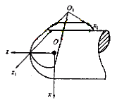
Fig.1 Principle of rake face machining

The rake face machining principle plays a crucial role in ensuring efficient cutting. The edge curve of a ball-end mill should follow an "S"-shaped spherical curve, which is the intersection between the rake face and the spherical surface formed during machining. The principle of this machining process is illustrated in Figure 1. During the operation, the grinding wheel rotates around a fixed axis O1, while the workpiece (the ball-end cutter being machined) rotates about its own axis Oz. The envelope surface generated by the relative motion of the grinding wheel forms the rake face. To develop a mathematical model for the rake face, coordinate systems s=[O;x,y,z] and s1=[O1;x1,y1,z1] are established, attached to the workpiece and the grinding wheel respectively. The transformation equations between these two systems are derived based on geometric parameters such as the radius of the grinding wheel, its angular half-angle, and the distance between the wheel and the center of rotation. These equations help describe the position and orientation of the grinding wheel relative to the workpiece.

1

The blade curve and parameter optimization are critical for achieving an ideal "S"-shaped edge. A spherical surface equation is used to define the boundary of the ball-end cutter, and the intersection with the rake face determines the edge curve. Optimization variables such as the position of the grinding wheel, the rotational speed ratio, and the wheel radius are adjusted to achieve the desired shape.

1
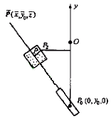
Figure 2 flank machining principle

For the flank face machining, the profile must pass through the edge curve while maintaining sufficient relief angle. The principle of this process is shown in Figure 2. A fixed point P0 on the y-axis and a moving point P2 on the edge curve define the trajectory of the plane curve used for grinding. By calculating the direction vector and applying geometric transformations, the path of the grinding wheel is determined, ensuring accurate material removal. The resulting mathematical models are more concise than those found in other documents, making them easier to implement and adapt for different tool specifications. This flexibility offers clear advantages in terms of efficiency and cost-effectiveness. Finally, the paper concludes that the non-numerical machining method has been successfully applied in practice, leading to the development of a series of ball-end cutters. These tools have been commercialized and demonstrate the potential for low-cost mass production. Furthermore, the principles outlined in this paper can be extended to other specialized rotary milling cutters, offering broader industrial applications. However, it is important to note that this paper only presents the fundamental framework, and further customization is required for real-world implementation.

Continuous Grain Powder Coating

Continuous grain powder coating

Continuous grain powder coating,net grain,Continuous grain

HLM Powder Coating CO,.Ltd , https://www.holymepowder.com

This entry was posted in on