The engineering system has an important position and determines the operating costs of the entire system. In order to reduce the cost of stripping, throwing blasting technology has been increasingly used in open-pit rock stripping projects since the 1960s [1-2]. Throwing blasting can directly throw 30%~65% of the blasting quantity into the gob by appropriately increasing the drilling and blasting cost, thereby greatly reducing the shovel loading and transportation costs, reducing the comprehensive stripping cost by more than 30%, and speeding up The speed of stripping engineering has obvious efficiency and economic benefits. This paper analyzes in detail the various influencing factors of throwing blasting to optimize the throwing
Throwing blasting effect [3-6].
1 Project Overview
In the open-air stripping project of the first column of the first cloud mining company, the northern end of the rock pillar is the original open pit of the closed pit. The bottom of the pit is -18m high, and the belt is connected with the ground crushing station. In order to reduce the cost of shovel loading and automobile transportation of blasting rock mass, in the appropriate width range of the southern slope (150m elevation) near the open pit, the throwing blasting technology is adopted to moderately increase the amount of blasthole charge, and the open pit is the free surface. Part of the rock blasting was directly thrown into the open pit, and the rest of the rock was dumped into the open pit by backhoeing and transported to the ground crushing station by the belt inside the pit. The throwing blast is shown in Figure 1.

The first cloud of iron ore underground stope is currently in the production stage, about 260m away from the blast area, should be strictly controlled blasting vibration, to avoid the impact on underground workings. Based on various factors, the single blasting dose of the mine is limited to less than 10t, which is suitable for single-hole single-shot.
2 blasting parameter design
The blasting design should fully reflect the purpose and requirements of the project, consider the mechanical equipment, technical strength and similar engineering experience, combined with the characteristics of the blasting project and the surrounding environment to meet the requirements of project quality, cost, schedule and safety.
2.1 step parameters
According to a number of experimental studies conducted by McDonald et al. [7] in the Rietspruit open-pit mine, the throwing rate P is linear with H/B, ie
![]()
When the step width is constant, when the step height or the step height is determined, the step width is reduced, and the throwing rate can be increased. The height of the steps is limited by the conditions of the site and the conditions of the mine drilling equipment and the shovel machinery. Therefore, the step height should generally be determined first. After the height of the step is determined, the use of a small step width, that is, a narrow stop field, can effectively increase the throwing rate, but the use of a wide stop has the advantages of high scraping efficiency, small single consumption of explosives, and small secondary processing. Therefore, the comprehensive evaluation of the economic benefits of throwing blasting is not only to pursue a higher throwing rate, but also to determine a reasonable H/B value based on both the improvement of the throwing rate and the advantages of the wide stop. The H/B value commonly used in mines is 0.7 to 1.0.
In addition, the determination of the height H of the step and the width B of the mining belt should also take into account the conditions of the mine production equipment, the conditions of the mining site and other restrictions. The project limits the amount of single blasting to no more than 10t.

Where q is the explosive unit consumption, taking 0.7kg/m3; V is the single blasting step volume, m3; L is the step length, m.
Combining the formula (2), the formula (3), and the appropriate H/B value, the step height H = 15 m, the step width B = 15 to 20 m, and the step length L = 48 to 64 m are determined.
2.2 blasthole angle
In the throwing blasting, the inclined blasthole should be adopted. Compared with the vertical blasthole, the inclined blasthole has a smaller resistance line in the lower part of the step, and most of the steps can be ejected at an elevation angle, which can enhance the blasting effect and increase the throwing rate. 2 is shown.

In addition, the inclined blasthole also has the following advantages: 1 is beneficial to the propagation of explosive energy in the rock, improving energy utilization; 2 the step slope after blasting is relatively more stable, improving production safety; 3 the length of a single blasthole is increased, With more explosives, the hole spacing and row spacing can be increased to reduce the drilling cost under the same explosive unit consumption.
The inclined blastholes are mostly 70°~80°. If the angle is reduced, the drilling will be more difficult, the drilling efficiency will be reduced, and the charging is not conducive to the blasting. According to the conditions of the open pit slope, the angle of the blasthole is determined to be α=70°, which is parallel to the angle of the slope.
2.3 Aperture
Large-aperture blastholes have shown superiority in terms of increasing production capacity and reducing drilling and blasting costs. However, when the single consumption of explosives is constant, the use of a large aperture will increase the pitch and the distance of the holes, which makes the throwing difficulty more difficult. Therefore, the aperture in the throwing blasting is generally less than 270 mm. Considering that the project has a small amount of blasting and the existing drilling equipment conditions of the Shouyun Mine, the aperture is determined to be 150 mm.
2.4 Explosive unit consumption
Reasonable explosive consumption q should be based on the requirements of rock hardness and blasting block, refer to B. H. The Kutunetsov rock blasting scale and the rock blasting fragmentation scale are selected. In some cases, it is also feasible to use the engineering analogy method to determine. In the step-throwing blasting, the explosive not only breaks the rock, but also throws it out as much as possible, so the required explosive consumption is higher than the general blast.
The rock in the blasting area of ​​the rock column is mainly composed of slanted gneiss and alkali long gneiss, and is mixed with common granitic lithology, dense and complete.
In the conventional conventional step blasting, the single consumption of explosives is 0.45~0.50kg/m3, and the throwing blasting should increase the unit consumption appropriately. It is more reasonable to take about 0.70kg/m3.
2.5 padding length
In order to reduce the large block rate of the clogging section of the blasthole, and at the same time ensure that the blasting does not punch, and improve the energy utilization rate of the explosive explosion, the clogging length of the blasthole is
![]()
Where Ls is the packing length, m; D is the diameter of the blasthole, which is 0.15 m.
Calculated Ls = 4.5m.
2.6 minimum resistance line
The size of the minimum resistance line W has an effect on the degree of fragmentation and the ejection speed, and should not be too large.
![]()
Where W is the minimum resistance line, m; qL is the line charge density, kg/m, measured by field statistics, qL = 13.5kg/m. Calculated W = 3.99m, row spacing b should be less than 3.99m.
2.7 density factor
In the case of a certain total dose, reasonable row spacing and hole spacing can improve the effect of throwing blasting. In recent years, the blasthole arrangement of small resistance lines and large hole distances has been widely used in step blasting. The density coefficient is often above 2.0, which can effectively improve rock fragmentation and reduce the root rate. To some extent, it can also enhance the throwing effect. In the high step (H>30) throwing blast, the optimal throwing rate can be obtained when 1.45<m<1.55, and the throwing rate begins to decrease when m>1.6 [5]. Combined with the actual conditions of the project, it is proposed to take m=1.5~2.0, and the blasthole is 1m deep.

Where, Q is the charge of a single blasthole, kg; a is the pitch of the hole, m; b is the row spacing, m; L is the length of the blasthole, m; m is the density factor.
Calculated from the equations (6) to (9), it is preliminarily determined that a = 6.0 m and b = 3.5 m.
2.8 differential time
By using the hole-by-hole initiation technology to achieve millisecond blasting between the same row of blastholes and between rows, the blasting vibration can be significantly reduced, the bulk rate can be reduced, and a better throwing effect can be achieved. The reasonable delay time should be related to the hole distance and row spacing of the blasthole, and the general row delay time is larger than the delay time between the same row of holes. However, the delay time should not be too long, otherwise the explosion of the first explosion blasthole will damage the rear blasthole, causing harmful effects such as discontinuous detonation. Based on domestic and international experience, the interval between holes is tk=9~25ms, and the interval between rows is tp=75~200ms.
3 blasting network connection
High-strength, high-precision detonator detonators are increasingly used in hole-by-hole detonation networks due to their small error and high reliability. Considering the cost control and the existing blasting equipment in the mine, it is proposed to use the ordinary detonating tube detonator to achieve the effect of hole-by-hole detonation through reasonable design.
According to the step parameters and the mesh parameters, the steps are arranged with 5 rows of blast holes, and each row is arranged with about 10 blast holes and triangular cloth holes. The lower hole of the detonator of the high-end detonator is used in the hole, and the detonator of the low-end detonator outside the hole is bound to the double-type explosion network. MS11, MS12, MS13, MS14, MS15 detonators are used in the first row to the fifth row of holes, and the surface is connected to the detonator.
With the MS2 detonator, the delay difference combination of the network "inter-row difference, hole indirect force" is used to make the adjacent blastholes have a certain detonation time interval to achieve the actual hole-by-hole detonation effect. Taking into account the remaining length of the detonator detonating tube in the hole at the surface, the five rows of blastholes are divided into two groups. The network connection is shown in Figure 3.

When the first detonator was detonated, the detonator connected to the outside of the hole had all been detonated, and there was no need to consider the damage caused by the rock displacement caused by the blast. In order to further improve the reliability of the network, the following two points should be noted: a double detonator is used in one hole, and a double network double detonator is used outside the hole; 2 the connecting detonator is covered with gravel to prevent the detonator fragments from interrupting the detonating tube.
4 conclusions and recommendations
(1) Conclusion. 1The blasting vibration is small, which has no effect on the normal production of the underground, and the slope is stable and safe; 2 the blasting throwing rate is 30%~40%, and the comprehensive stripping cost can be reduced by 25%~30% compared with the traditional blasting method; Reduce the root rate and bulk rate, thus reducing the amount of secondary crushing, and have obvious economic benefits; 4 within a certain single burst, through reasonable network design, using ordinary detonator tube detonator, can achieve high strength, high The detonating effect and reliability of the precision detonator tube detonator.
(2) Suggestions. 1 The throwing effect of the first row of holes in the throwing blast has an important influence on the throwing of the rear row, which can reasonably increase the amount of charge or reduce its resistance line; 2 the last row and the side row of holes can appropriately reduce the amount of charge Or use an air spacer to stage the charge to reduce backlash and side punch.
references
[1] Pan Jingwei. Discussion on the application of throwing blasting in open-air step mining [J]. Chemical Mining Technology, 1992 (6): 1-4.
[2] Zhang Youti, Fu Hongxian, Wang Qirui, et al. Analysis of the parameters of throwing blasting and stripping step mining————The fourth series of papers on open pit mine stripping mining method [J]. Journal of China University of Mining and Technology, 2003(1): 30-33.
[3] Li Kemin, Zhang Youti, Fu Hongxian. Analysis [J] open cast coal mine blasting parameters. Journal of Mining and Safety Engineering, 2006(4): 423-426.
[4] Guo Zhaohua. Research and application of throwing blasting technology in open pit mine [J]. Coal Engineering, 2008 (1): 31-35.
[5] Li Xianglong. The influence of hole spacing and row spacing on the throwing rate of high-step throwing blasting [J]. Journal of Beijing Institute of Technology, 2011 (11): 1265-1269.
[6] Ma Li, Li Kemin, Ding Xiaohua, et al. Study on the influencing factors of throwing distance of throwing blasting rock mass [J]. Engineering Blasting, 2013(s1): 50-53.
[7]GrippoAP. Howtogetmorecastperblast [J]. CoalAge, 1984, 89 (12): 63-69.
Article source: "Modern Mining"; 2016.9;
Author: He Huiming, Wang Hongjun, Guo Rui; College of Science and Technology, Beijing University of Civil and Environmental Engineering;
Copyright:
Length: 6m-18m
Top diameter: 150mm-230mm/by buyer
Taper: 1:75/by buyer
Advantage: high quality, easy operation
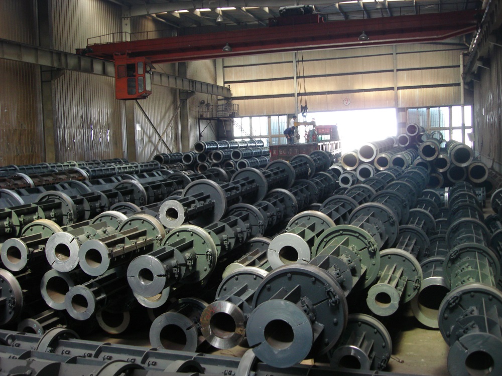
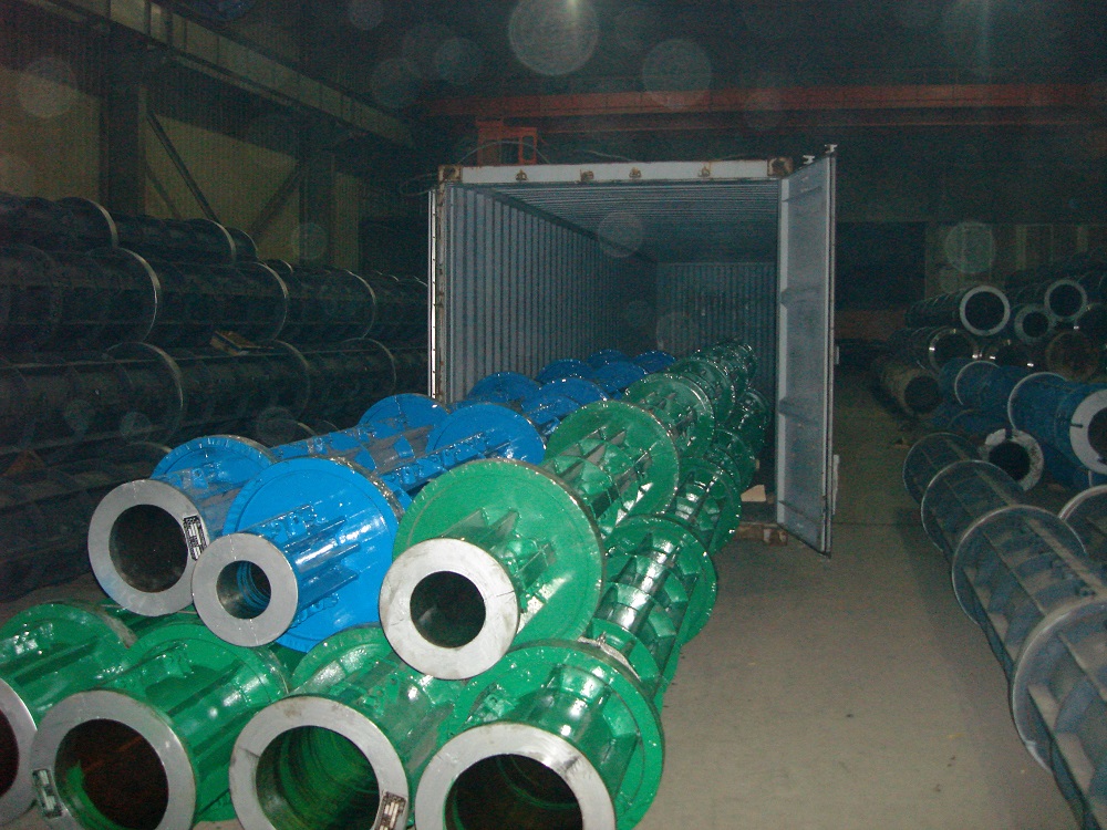
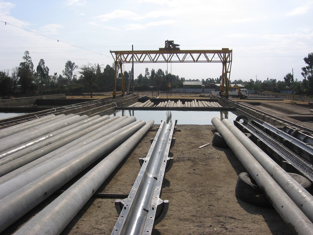
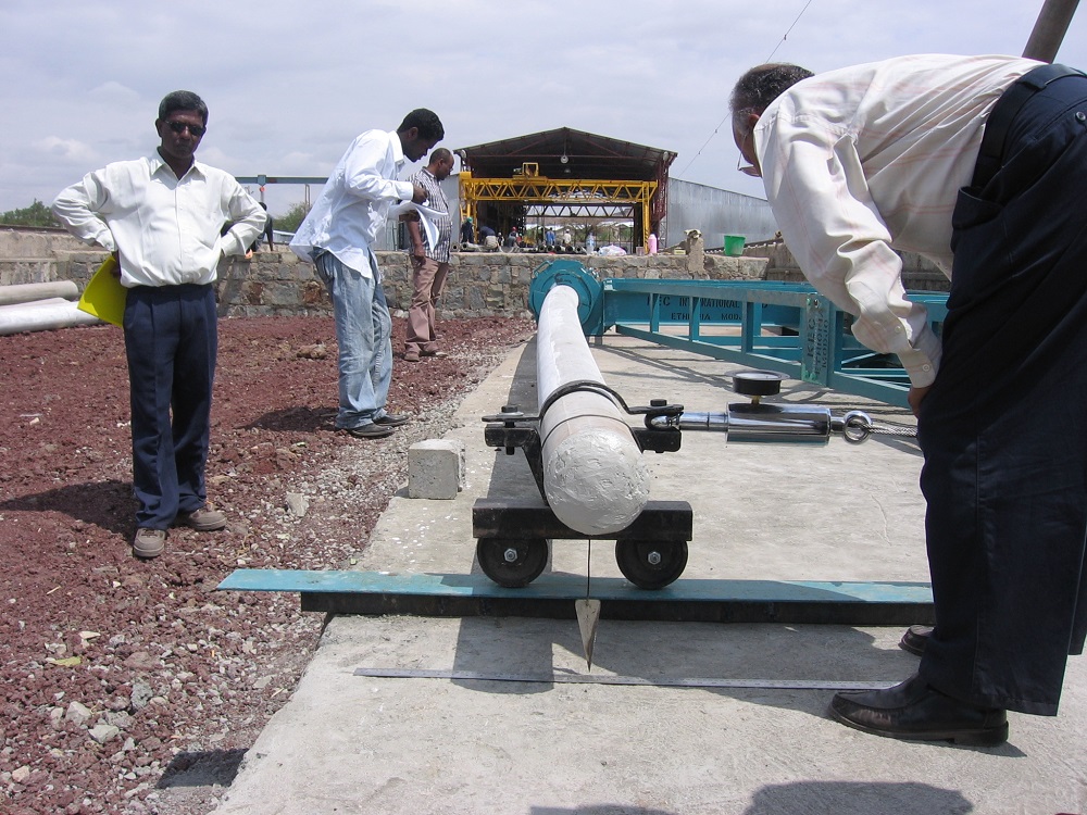
Pre-stressed concrete pole mould is used for electronic concrete pole making. Its mainly manufacture technology is longitudinal tension by steel wires. Then it can squeeze out the excess water in the concrete under the centrifugal force. Thus, it can greatly improve the concrete density and strength.
In order to form concrete more quickly to meet the design strength of more than 70%, steam curing can be carried out so as to shorten the mould-releasing cycle.
Our factory produces two categories of Pre-stressed concrete pole steel moulds, DMZ&DMD. The Pre-stressed Electric Poles by this series equipment comply with the China Standard JC/T364-2001.

Features:
1. Welding technology, which enhances the smooth finish of the mould wall, and eliminates the uneven traces of rivet holes. So the concrete poles appearance will be improved significantly.
2. The cylinder is changed to U-type longitudinal stiffeners which can greatly increase the stiffness and flexural strength of the Steel Mould,
3. Install the slot with rubber sealing strip, in order to prevent leakage to ensure quality.
The Technical parameter:
Inside Diameter(mm)
Wheel Distance(mm)
Wheel Diameter (mm)
Length(mm)
Ø100
2000
Ø600
6-7
Ø110
2000
Ø600
6-7
Ø120
2000
Ø600
6-8
Ø130
2000
Ø600
6-8
Ø150
2000
Ø600
6-10
Ø170
2000
Ø600
6-12
Ø190
2000
Ø600
7-12
Ø190
2000
Ø650
15-18
Ø230
2000
Ø650
6-9
Ø310
2000
Ø650
6-9
Ø350
2000
Ø680
6-9
Ø390
2000
Ø750
6-9


Centrifugal Machine,Spun Prestressed Pole Mould ,Spc Pole Mould,Spc Pole Mould In Bangladesh
Jiangsu Haiheng Building-Materials Machinery Co.,Ltd , https://www.jshaiheng.com